Deprecated: Function Yoast\WP\SEO\Conditionals\Schema_Blocks_Conditional::get_feature_flag is deprecated since version Yoast SEO 20.5 with no alternative available. in /home1/ifrhmnmy/public_html/archicrewindia/wp-includes/functions.php on line 6031
Deprecated: Function Yoast\WP\SEO\Conditionals\Schema_Blocks_Conditional::get_feature_flag is deprecated since version Yoast SEO 20.5 with no alternative available. in /home1/ifrhmnmy/public_html/archicrewindia/wp-includes/functions.php on line 6031
Deprecated: Function Yoast\WP\SEO\Conditionals\Schema_Blocks_Conditional::get_feature_flag is deprecated since version Yoast SEO 20.5 with no alternative available. in /home1/ifrhmnmy/public_html/archicrewindia/wp-includes/functions.php on line 6031 Structure System of High Rise Building - ArchiCrew India
Skip to content
The steel systems developed between 1960 to 1975, fit a logical evolutionary pattern with one development leading to another, and each time forming a new system.
Although the primary motivation for these developments was structural efficiency, the systems also offered great opportunities for Structuralist facade architecture.
Therefore, to provide resistance to the combined effects of horizontal and vertical loads in a multistorey building, several structural systems have been adopted.
The designed structure gives more compatibility when used with adequate structural material.
CRITERIA FOR THE CHOICE OF MATERIAL:
Floor spans
Height of the building
Weight of the building if it is too high.
Imposed loads
Cross-sectional dimensions of columns
Time of construction
Fire resistance
CLASSIFICATION OF STRUCTURAL SYSTEMS IN TALL BUILDINGS
Structural systems of tall buildings can be divided into two broad categories:
– Interior structures
– Exterior structures.
A system is categorized as an interior structure when the major part of the lateral load resisting system is located within the interior of the building.
Likewise, if the major part of the lateral load resisting system is located at the building perimeter, a system is categorized as an exterior structure.
It should be noted,
-that any interior structure is likely to have some minor components of the lateral load-resisting system at the building perimeter,
-and any exterior structure may have some minor components within the interior of the building.
On occasions, an exterior structure may be combined with an interior one.
INTERIOR STRUCTURES
MOMENT-RESISTING FRAMES
The moment-resisting frame (MRF) consists of horizontal (girder) and vertical (column) members rigidly connected together in a planar grid form.
Such frames resist load primarily through the flexural stiffness of the members
The size of the columns is mainly controlled by the gravity loads that accumulate towards the base of the building giving rise to progressively larger column sizes towards the base from the roof.
The size of the girders, on the other hand, is controlled by the stiffness of the frame to ensure the acceptable lateral sway of the building.
Although the gravity load is more or less the same in all typical floors of a tall building, the girder sizes need to be increased to increase the frame stiffness.
Likewise, columns already sized for gravity loads need to be slightly increased to increase the frame stiffness as well.
MRFs can be located in or around the core, on the exterior, and throughout the interior of the building along grid lines.
BRACED FRAMES
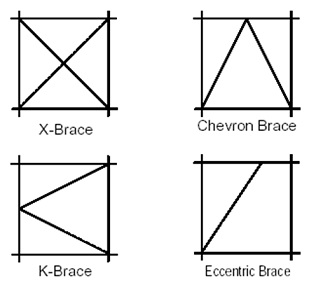
Braced frames are laterally supported by vertical steel trusses, also called shear trusses, which resist lateral loads primarily through axial stiffness of the members.
These act as vertical cantilever trusses where the columns act as chord members and the concentric K, V, or X braces act as web members.
Braced frames are generally located in the service and elevator core areas of tall buildings. The frame diagonals are enclosed within the walls.
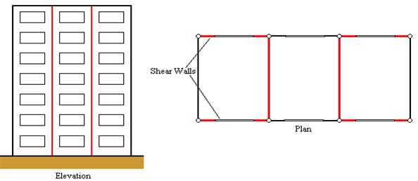
3. REINFORCED CONCRETE PLANAR SOLID OR COUPLED SHEAR WALLS
These systems have been one of the most popular systems used for high-rise construction to resist lateral forces caused by wind and earthquakes.
Shear walls are treated as vertical cantilevers fixed at the base.
When two or more shear walls in the same plane are interconnected by beams or slabs, the total stiffness of the system exceeds the sum of the individual wall stiffnesses.
This is so because the connecting beam forces the walls to act as a single unit by restraining their individual cantilever actions.
These are known as coupled shear walls.
Shear walls used in tall office buildings are generally located around service and elevator cores, and stairwells.
Rigid frame systems are not efficient for buildings over 30 stories in height, On the other hand, concrete shear walls alone may provide resistance for buildings up to about 10 or 35 stories.
This type of system has wide applications for buildings up to about 40 to 70 stories in height.
EXTERIOR STRUCTURES
The nature of building perimeters—
– more structural significance in tall buildings due to their very tallness, which means greater vulnerability to lateral forces, especially wind loads.
Thus, it is quite desirable to concentrate as much lateral load-resisting system components as possible on the perimeter of tall buildings to increase their structural depth, and, in turn, their resistance to lateral loads.
1. TUBE STRUCTURES
It is defined as a three-dimensional structural system utilizing the entire building perimeter to resist lateral loads.
The earliest application of the tubular notion is attributed to Fazlur Khan, who thought of this concept in 1961 (Ali, 2001)
He designed the 43-story DeWitt-Chestnut Apartment Building in Chicago, completed in 1965, the first known building designed as a framed tube.
In the tube system the building perimeter, rather than the central core, is used for the lateral system.
Such systems are known as external tubes. External tube systems involve tying the perimeter columns of the building together to form a hollow tube. Thus, The tube is the name given to the systems where to resist lateral loads (wind, seismic, etc.) a building is designed to act like a three-dimensional hollow tube, cantilevered perpendicular to the ground.
Tubular forms have several types depending upon the structural efficiency that they can provide for different heights.
1a) FRAMED TUBE SYSTEM:
In a framed tube system, which is the basic tubular form, the building has closely spaced columns and deep spandrel beams rigidly connected together throughout the exterior frames.
Depending upon the structural geometry and proportions, exterior column spacing should be from 5 to 15ft (1.5 to 4.5m) on centres.
Practical spandrel beam depths should vary from 24 to 48in (600 to 1200mm).
The resulting structural organization not only provides a structural expression of the façade, thereby defining the architectural fenestration, but also can cut costs by eliminating the need for mullions of the curtain wall fully or partly.
The purpose of the optimal design of a framed tube is to aim for more cantilever-type behaviour of the structure within reasonable and practical limits.
1b) BRACED/TRUSSED TUBE SYSTEM
As the framed tube becomes progressively inefficient over 60 stories since the web frames begin to behave as conventional rigid frames so it came into being.
A braced tube is a variation of the framed tube and was first applied to the 100-story John Hancock Center of 1970 in Chicago (Ali, 2001).
This concept stems from the fact that instead of using closely spaced perimeter columns, it is possible to stiffen the widely spaced columns by diagonal braces to create wall-like characteristics.
John Hancock Center in Chicago
Consequently, beam and column designs are controlled by bending action, resulting in a large size.
A braced tube overcomes lateral loads by stiffening the perimeter frames in their own planes.
The braces also collect gravity loads from floors and act as inclined columns.
Therefore, the columns can be more widely spaced and the sizes of spandrels and columns can be smaller than those needed for framed tubes, allowing for larger window openings than in the framed tubes.
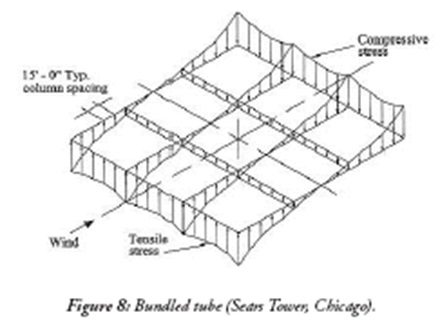
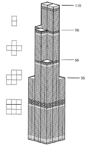
1c) BUNDELED TUBE SYSTEM
A bundled tube is a cluster of individual tubes connected together to act as a single unit.
For very tall structures, a single framed tube is not adequate, since the width of the building at its base should be large to maintain reasonable slenderness (i.e., height-to-width) ratio such that the building is not excessively flexible and does not sway too much.
For such a structure, the three-dimensional response of the structure could be improved for strength and stiffness by providing cross walls or cross frames in the building.
The 110-story Sears Tower was the first bundled tube structure in which nine steel-framed tubes are bundled at the base, some of which are terminated at various levels along with the building’s height with two tubes continuing between the 90th floor and the roof
Such flexibility of organizing the floor areas, from very large at the base to much smaller at the top, gave the bundled tube system an added advantage.
The bundled tube system thus offers great freedom in architectural planning by creating a powerful vocabulary for a variety of existing building forms.
Besides, it is worth noting that to behave as a bundled tube the individual tubes could be of different shapes, such as rectangular, triangular, or hexagonal as is demonstrated by One Magnificent Mile of 1983 in Chicago.
1d) TUBE-IN-TUBE
The stiffness of a framed tube can also be enhanced by using the core to resist part of the lateral load resulting in a tube-in-tube system.
The floor diaphragm connecting the core and the outer tube transfer the lateral loads to both systems.
The core itself could be made up of a solid tube, a braced tube, or a framed tube.
Such a system is called a tube-in-tube, an example of which is the 52-story One Shell Plaza of 1971 in Houston, Texas.
It is also possible to introduce more than one tube inside the perimeter tube.
1e) HYBRID SYSTEM
A varied category of structures where the basic concept of the tube is used, but supplemented by other structural support methods.
These systems are used where the slenderness of the building is such that a single system cannot provide adequate strength or stiffness.
In theory, almost any combination of systems is possible, providing that the stiffnesses are approximately equal.
2. DIAGRID SYSTEMS
Early designs of tall buildings recognized the effectiveness of diagonal bracing members in resisting lateral forces.
Most of the structural systems deployed for early tall buildings were steel frames with diagonal bracings of various configurations such as X, K, and chevron.
However, while the structural importance of diagonals was well recognized, the aesthetic potential of them was not appreciated since they were considered obstructive for viewing the outdoors.
Thus, diagonals were generally embedded within the building cores which were usually located in the interior of the building.
But trussed tube strategy as in John Hancock is much more effective than confining diagonals to narrower building cores.
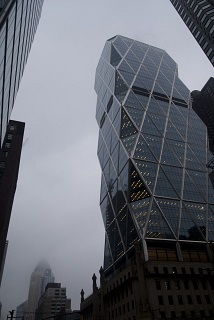
However, recently the use of perimeter diagonals – thus the term “diagrid” – for structural effectiveness and lattice-like aesthetics has generated renewed interest in architectural and structural designers of tall buildings.
Hearst Building, New York, USA
The difference between conventional exterior-braced frame structures and current diagrid structures is that, for diagrid structures, almost all the conventional vertical columns are eliminated.
This is possible because the diagonal members in diagrid structural systems can carry gravity loads as well as lateral forces due to their triangulated configuration in a distributive and uniform manner.
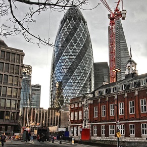
St. Mary Axe building showing diagrid structure system
Diagrid structures are more effective in minimizing shear deformation because they carry shear by axial action of the diagonal members.
The diagrid structure provides both bending and shear rigidity.
An ultra-tall building currently being designed by Skidmore, Owings, and Merrill is the Lotte Super Tower in Korea, which employs a diagrid multi-planar façade.
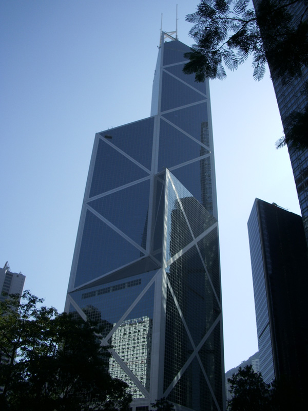
3. SPACE TRUSSES,
Space truss structures are modified braced tubes with diagonals connecting the exterior to the interior.
In a typical braced tube structure, all the diagonals, which connect the chord members
– are located on the plane parallel to the facades.
However, in space trusses, some diagonals penetrate the interior of the building.
Examples include the Bank of China Tower of 1990 by I. M. Pei in Hong Kong.
4. SUPER FRAMES
A super-frame is composed of mega columns comprising braced frames of large dimensions at building corners, linked by multistory trusses at about every 15 to 20 stories.
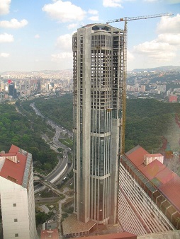
The concept of superframe can be used in various ways for tall buildings, such as the 56-story tall Parque Central Complex Towers of 1979 in Caracas, Venezuela.
56-story tall Parque Central Complex Towers of 1979 in Caracas, Venezuela
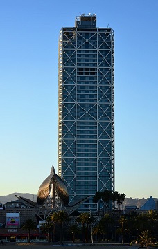
EXOSKELETON.
In exoskeleton structures, lateral load-resisting systems are placed outside the building lines away from their facades. Examples include Hotel de las Artes in Barcelona.
Hotel de las Artes in Barcelona
Due to the system’s compositional characteristics, it acts as a primary building identifier – one of the major roles of building facades in general cases.
Fireproofing of the system is not a serious issue due to its location outside the building line.
However, thermal expansion/contraction of the system, exposed to the ever-changing outdoor weather, and the systemic thermal bridges should be carefully considered during design.
CONCRETE CORES
The efficiency of the cores in any high-rise building is critical to the overall efficiency of the building and thereby the profitability of the proposed development.
Reinforced concrete cores have several advantages over steel-braced cores in this respect, but traditional methods of concrete construction are too slow for use in high-rise buildings.
This has led to the common use of jump or slip formed construction that incorporates working platforms and enclosed cells in which persons are required to work.
A slip form system can only construct the walls of the core as it advances, whereas a jump form system will allow simultaneous construction of the floors within the cores. As a result, the slip form system may require temporary bracing to isolated outstand walls.
1 thought on “Structure System of High Rise Building”


Pingback: ArchiCrew India